Modelica_StateGraph2
Information
 Library Modelica_StateGraph2 is a free Modelica package providing
components to model discrete event, reactive and
hybrid systems in a convenient way with deterministic hierarchical state diagrams.
For convenience, the abbreviation "StateGraph2" will be
often used for this library. An example model constructed with this
library is shown in the figure to the right.
Library Modelica_StateGraph2 is a free Modelica package providing
components to model discrete event, reactive and
hybrid systems in a convenient way with deterministic hierarchical state diagrams.
For convenience, the abbreviation "StateGraph2" will be
often used for this library. An example model constructed with this
library is shown in the figure to the right.
This library is inspired by Grafcet/Sequential Function Charts (SFC), Statecharts,
Safe State Machines (SSM) and Mode Automata, and utilizes Modelica as action language.
It has a similar modeling power as
these formalisms, e.g. synchronization of parallel executing branches
as in SFC (not easy in Statecharts), or suspending a hierarchical subgraph with one
transition and resuming at the same states afterwards when entering it again, as in Statechart (not possible in SFC). A StateGraph2 model is always deterministic due to
Modelicas "single assignment rule". Via special blocks in subpackage "Blocks",
actions can be defined in a graphical way depending on the active step.
In order to construct a new state machine, exactly one instance of either "Step"
or of "Parallel" must have parameter "initialStep = true".
The "Parallel" component is both used as "composite step" (so only one branch),
as well as "parallel step" (so several execution branches). The branches can be
synchronized (if parameter use_outPort = true) or can run unsynchronized
to each other (if parameter use_outPort = false).
For an introduction, have especially a look at:
- Tutorial
provides an overview of the library inside the User's Guide.
- Examples
provides simple introductory examples as well as involved application examples.
- ComparisonWithStateGraph1
summarizes the enhancements with respect to the previous version of
Modelica.StateGraph.
This library is implemented with Modelica 3.1 and utilizes non-standard extensions to Modelica 3.1 as summarized
here.
It is planned to include this library as Modelica.StateGraph
in the Modelica Standard Library. The current Modelica.StateGraph library will be renamed
to ModelicaObsolete.StateGraph1 and a conversion script will be provided (an automatic
conversion from the "old" to the "new" version is not possible and therefore both
libraries must be kept).
Licensed by DLR and Dynasim under the Modelica License 2
Copyright © 2003-2009, DLR and 2007-2009, Dynasim AB
This Modelica package is free software and
the use is completely at your own risk;
it can be redistributed and/or modified under the terms of the
Modelica license 2, see the license conditions (including the
disclaimer of warranty)
here
or at
http://www.Modelica.org/licenses/ModelicaLicense2.
Package Content
| Name | Description |
|---|
 UsersGuide UsersGuide
| User's Guide |
 Examples Examples
| Examples to demonstrate the usage of the Modelica_StateGraph2 library |
 Step Step
| Step (optionally with initial step and/or activePort) |
 Transition Transition
| Transition between steps (optionally with delayed transition and/or condition input port) |
 LoopBreakingTransition LoopBreakingTransition
| Transition to break loops by introducing an artificial time delay (immediately fire and then wait) |
 Parallel Parallel
| Composite or parallel step |
 PartialParallel PartialParallel
| Partial compont to construct a parallel submodel via inheritance |
 Blocks Blocks
| Input/output blocks that are designed for StateGraph2 but shall be included in the Modelica Standard Library |
| Internal
| Internal utility models (should usually not be used by user) |
Step (optionally with initial step and/or activePort)
Information
A Step is the graphical representation of a state and is said to be either
active or not active. A StateGraph2 model is comprised of one or more
steps that may or may not change their states during execution.
The input port of a Step (inPort) can only be connected to the output port
of a Transition, and the output port of a Step (outPort) can only be connected
to the input of a Transition. An arbitrary number of input and/or output
Transitions can be connected to these ports.
The state of a step is available via the output variable active that can
be used in action blocks (e.g. "step.active"). Alternatively, via parameter
"use_activePort" the Boolean output port "activePort" can be enabled.
When the step is active, activePort = true, otherwise it is false. This port can
be connected to Boolean action blocks, e.g., from
Modelica_StateGraph2.Blocks.MathBoolean.
Every StateGraph2 graph
must have exactly one initial step. An initial step is defined by setting parameter initialStep
at one Step or one Parallel component to true. The initial step is visualized by a
small arrow pointing to this step.
In the following table different configurations of a Step are shown:
| Parameter setting |
Icon |
Description |
|---|
| Default step |
 |
If the step is active, the public Step variable "active" is true
otherwise, it is false. An active Step is visualized by a green
fill color in diagram animation. |
| use_activePort = true |
 |
If the step is active, the connector "activePort" is true
otherwise, it is false (the activePort is the small, violet, triangle
at the rigth side of the Step icon). Actions may be triggered, e.g., by connecting block
MultiSwitch
to the activePort. |
| initialStep = true |
 |
Exactly one Step or Parallel component in a StateGraph2 graph
must have "initialStep = true". At the first model evaluation
during initialization, "active" is set to true for
the initial Step or the initial Parallel component, i.e.,
the respective component is activated. |
The inPort and the outPort connectors of a Step are "vectors of connectors".
How connections to these ports are automatically handled in a convenient way is sketched
here
in the tutorial.
Parameters
| Type | Name | Default | Description |
|---|
| Boolean | initialStep | false | =true, if initial step (graph starts at this step) |
| Boolean | use_activePort | false | =true, if activePort enabled |
Connectors
| Type | Name | Description |
|---|
| Step_in | inPort[nIn] | Port for zero, one, or more input transitions |
| Step_out | outPort[nOut] | Port for zero, one, or more output transitions |
| output BooleanOutput | activePort | = true if step is active, otherwise the step is not active |
Modelica definition
model Step "Step (optionally with initial step and/or activePort)"
  parameter Integer nIn(min=0)=0 "Number of input connections";
  parameter Integer nOut(min=0)=0 "Number of output connections";
  parameter Boolean initialStep = false
    "=true, if initial step (graph starts at this step)";
  parameter Boolean use_activePort = false "=true, if activePort enabled";

  Modelica_StateGraph2.Internal.Interfaces.Step_in inPort[nIn]
    "Port for zero, one, or more input transitions";
  Modelica_StateGraph2.Internal.Interfaces.Step_out outPort[nOut]
    "Port for zero, one, or more output transitions";
  Modelica.Blocks.Interfaces.BooleanOutput activePort = active if use_activePort
    "= true if step is active, otherwise the step is not active";
  output Boolean active
    "= true if step is active, otherwise the step is not active";

protected
  Boolean newActive(start=initialStep, fixed=true)
    "Value of active in the next iteration";
  Boolean oldActive(start=initialStep, fixed=true)
    "Value of active when CompositeStep was aborted";

  Modelica_StateGraph2.Internal.Interfaces.Node node
    "Handles rootID as well as suspend and resume transitions from a Modelica_StateGraph2";

  Boolean inport_fire;
  Boolean outport_fire;

equation
  // set active state
  inport_fire  = Modelica_StateGraph2.Blocks.BooleanFunctions.anyTrue(
                                            inPort.fire);
  outport_fire = Modelica_StateGraph2.Blocks.BooleanFunctions.anyTrue(
                                            outPort.fire);
  newActive = if node.resume then oldActive else
                 inport_fire or (active and not outport_fire) and not node.suspend;
  active = pre(newActive);

  // Remember state for suspend action
  when node.suspend then
    oldActive = active;
  end when;

  // Report state to output transitions
  for i in 1:nOut loop
     outPort[i].available = if i == 1 then active and not node.suspend else
                               outPort[i-1].available and not outPort[i-1].fire and not node.suspend;
  end for;

  inPort.checkUnaryConnection = fill(true, nIn);
  outPort.checkOneDelayedTransitionPerLoop = fill(
    Modelica_StateGraph2.Internal.Utilities.propagateLoopCheck(inPort.checkOneDelayedTransitionPerLoop),
    nOut);

  // Handle initial step and propagate node information from inPort to node

   for i in 1:nIn loop
      Connections.branch(inPort[i].node, node);
      inPort[i].node = node;
   end for;

  if initialStep then
     Connections.uniqueRoot(node, "
The StateGraph has a wrong connection structure. Reasons:
(1) The StateGraph is initialized at two different locations (initial steps or entry ports).
(2) A transition is made wrongly out of a Parallel component.
(3) A transition is made between two branches of a Parallel component.
All these cases are not allowed.
");

     node.suspend = false;
     node.resume  = false;
   else
    // Check that connections to the connector are correct
     assert(nIn > 0, "Step is not reachable since it has no input transition");

     // In order that check works (nIn=0), provide the missing equations
     if nIn==0 then
        node.suspend = false;
        node.resume  = false;
     end if;
  end if;

  // Propagate node information from node to outPort
  for i in 1:nOut loop
     Connections.branch(node, outPort[i].node);
     outPort[i].node = node;
   end for;

  // Check that all graph connectors are connected
  for i in 1:size(inPort,1) loop
     if cardinality(inPort[i])==0 then
        inPort[i].fire = true;
        inPort[i].checkOneDelayedTransitionPerLoop = true;
        assert(false,"
An element of the inPort connector of this step is not connected. Most likely, the Modelica tool
has a bug and does not correctly handle the connectorSizing annotation in a particular case.
You can fix this by removing all input connections to this step and by manually removing
the line 'nIn=...' in the text layer where this step is declared.
");
     end if;
  end for;

  for i in 1:size(outPort,1) loop
     if cardinality(outPort[i])==0 then
        outPort[i].fire = true;
        assert(false,"
An element of the outPort connector of this step is not connected. Most likely, the Modelica tool
has a bug and does not correctly handle the connectorSizing annotation in a particular case.
You can fix this by removing all output connections to this step and by manually removing
the line 'nOut=...' in the text layer where this step is declared.
");
     end if;
  end for;
end Step;
Transition between steps (optionally with delayed transition and/or condition input port)
Information
 To define a possible change of states, a Transition is connected to the output of the preceding Step and to the input of the succeeding Step, see figure to the right, where Transition t1 defines the transition from Step s1 to Step s2. Note: A Transition has exactly one preceding and one succeeding Step. A Transition is said to be enabled if the preceding step is active. An enabled transition is said to be fireable when the Boolean condition defined in the parameter menu of the transition is evaluated to true. This condition is also called Transition condition and is displayed in the icon of the Transition (e.g., "time > 1" is the condition of Transition t1). When parameter use_conditionPort is set, the Transition condition is alternatively defined by a Boolean signal that is connected to the enabled conditionPort.
A fireable transition will fire immediately. In the figure to the right, t1 fires when s1 is active and time is greater than one, i.e., s1 becomes inactive and s2 becomes active.
The firing of a transition can optionally also be delayed for a certain period of time defined by parameter "waitTime". See, e.g., t2 in the figure to right, that is delayed for one second before it may fire, given that the condition remains true and the preceding Step remains active during the entire delay time.
In the following table different configurations of a Transition are shown:
| Parameter setting |
Icon |
Description |
|---|
| Default transition |
 |
The transition fires when the preceding step is active
and the expression "condition" in the parameter menu is true. |
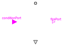
| use_conditionPort = true |
 |
The transition fires when the preceding step is active
and connector "conditionPort" is true. |
| delayedTransition = true |
 |
The transition fires after the delay time "waitTime" (here: 1.23 s),
if the preceding step was active, and "condition = true"
during the entire delay time. |
| use_firePort = true |
 |
Connector "firePort" is true when the transition fires.
Actions may be triggered, e.g., by connecting block
MultiSwitch
to the firePort. |
loopCheck = false
(in "Advanced" tab) |
 |
It is not checked whether the loop in which this Transition
is used, has at least one delayed transition.
Use this option only, if you are completley sure that
infinite event looping is not possible in this loop.
Consider to use
LoopBreakingTransition
instead! |
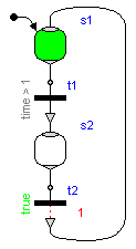
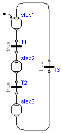 At an event instant, an iteration occurs, due to the Modelica semantics (= whenever a new event occurs, the model is re-evaluated). This means that Transitions keep firing along a connected graph, as long as the firing conditions are true. In principal, it is therefore possible that infinite event looping occurs.
A simple example of this kind is shown in the figure to the right. Here, all Transition conditions are true and therefore all Transitions would fire forever at the initial time. This is, however, no valid StateGraph2 model and will result in a translation error, since it is required that a StateGraph2 model has at least one delayed Transition per loop.
This means that one of T1, T2, or T3, must have parameter delayedTransition=true. Since event iteration stops at a delayed Transition, infinite event looping cannot occur. This also means that at one time instant every Transition can fire at most once and therefore the number of model evaluations at an event instant is bounded by the number of Transition components.
At an event instant, an iteration occurs, due to the Modelica semantics (= whenever a new event occurs, the model is re-evaluated). This means that Transitions keep firing along a connected graph, as long as the firing conditions are true. In principal, it is therefore possible that infinite event looping occurs.
A simple example of this kind is shown in the figure to the right. Here, all Transition conditions are true and therefore all Transitions would fire forever at the initial time. This is, however, no valid StateGraph2 model and will result in a translation error, since it is required that a StateGraph2 model has at least one delayed Transition per loop.
This means that one of T1, T2, or T3, must have parameter delayedTransition=true. Since event iteration stops at a delayed Transition, infinite event looping cannot occur. This also means that at one time instant every Transition can fire at most once and therefore the number of model evaluations at an event instant is bounded by the number of Transition components.
If you have to artifically introduce a delay time in order to fulfill the requirement above, it is recommended to use the special
LoopBreakingTransition
that is designed for this case.
Note, it is still possible that infinite event looping occurs due to model errors in other parts of the model. For example, if a user introduces an equation of the form "J = pre(J) + 1" outside of a when-clause, event iteration does not stop.
There are rare situations, where infinite event looping cannot occur even if there is no delayed transition in a loop. When you do not want to introduce an artifical time delay in a loop in this case, you can switch off the loop check by setting parameter "loopCheck = false" in the "Advanced" tab of the parameter menu of one Transition in this loop.
Parameters
| Type | Name | Default | Description |
|---|
| Boolean | use_conditionPort | false | = true, if conditionPort enabled |
| Boolean | condition | true | Fire condition (time varying Boolean expression) |
| Boolean | delayedTransition | false | = true, if transition fires after waitTime |
| Time | waitTime | 0 | Wait time before transition fires (> 0 required) [s] |
| Boolean | use_firePort | false | = true, if firePort enabled |
| Advanced |
| Boolean | loopCheck | true | = true, if one delayed transition per loop required |
Connectors
| Type | Name | Description |
|---|
| Transition_in | inPort | Input port of transition (exactly one connection to this port is required) |
| Transition_out | outPort | Output port of transition (exactly one connection from this port is required) |
| input BooleanInput | conditionPort | Fire condition as Boolean input. |
| output BooleanOutput | firePort | = true, if transition fires |
Modelica definition
model Transition
  "Transition between steps (optionally with delayed transition and/or condition input port)"
  parameter Boolean use_conditionPort = false
    "= true, if conditionPort enabled";

  input Boolean condition = true
    "Fire condition (time varying Boolean expression)";

  parameter Boolean delayedTransition = false
    "= true, if transition fires after waitTime";
  parameter Modelica.SIunits.Time waitTime = 0
    "Wait time before transition fires (> 0 required)";

  parameter Boolean use_firePort = false "= true, if firePort enabled";

  parameter Boolean loopCheck = true
    "= true, if one delayed transition per loop required";

  Modelica_StateGraph2.Internal.Interfaces.Transition_in inPort
    "Input port of transition (exactly one connection to this port is required)";

  Modelica_StateGraph2.Internal.Interfaces.Transition_out outPort
    "Output port of transition (exactly one connection from this port is required)";

  Modelica.Blocks.Interfaces.BooleanInput conditionPort if use_conditionPort
    "Fire condition as Boolean input.";

  Modelica.Blocks.Interfaces.BooleanOutput firePort = fire if use_firePort
    "= true, if transition fires";

  output Boolean fire "= true, if transition fires";
  output Boolean enableFire "= true, if firing condition is true";

protected
  constant Modelica.SIunits.Time minimumWaitTime = 100*Modelica.Constants.eps;
  Modelica.SIunits.Time t_start
    "Time instant at which the transition would fire, if waitTime would be zero";
  Modelica.Blocks.Interfaces.BooleanInput localCondition;
initial equation
  pre(enableFire) = false;
  pre(t_start) = 0;
equation
  // Handle conditional conditionPort
  connect(conditionPort, localCondition);
  if not use_conditionPort then
     localCondition = condition;
  end if;

  // Determine firing condition
  enableFire = localCondition and inPort.available;

  if delayedTransition then
     when enableFire then
        t_start = time;
     end when;
     fire = enableFire and time >= t_start + waitTime;
     outPort.checkOneDelayedTransitionPerLoop = true;
  else
     t_start = 0;
     fire = enableFire;
     if loopCheck then
        outPort.checkOneDelayedTransitionPerLoop = inPort.checkOneDelayedTransitionPerLoop;
     else
        outPort.checkOneDelayedTransitionPerLoop = true;
     end if;
  end if;

  inPort.fire  = fire;
  outPort.fire = fire;

  // Handling of node
  Connections.branch(inPort.node, outPort.node);
  outPort.node = inPort.node;

  // Asserts
  assert(not delayedTransition or
         delayedTransition and waitTime > minimumWaitTime,
        "Either set delayTransition = false, or set waitTime (= " + String(waitTime) + ") > " + String(minimumWaitTime));
end Transition;
Transition to break loops by introducing an artificial time delay (immediately fire and then wait)
Information
Every loop in a StateGraph2 model needs to have at least one delayed
transition. If this is not the case, a delay needs to be introduced
at one transition of a loop. The "LoopBreakingTransition" is
designed to replace an (immediate)
Transition
by a Transition that
fires immediately, and then waits in an internal step for the defined
delay time. The semantics is therefore slightly different if a Transition
with "delayedTransition = true" is used. In the latter case, the transition
only fires after the delay time and the fire condition must remain true
during this time period.
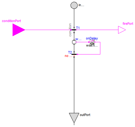
A LoopBreakingTransition is just a convenient short hand notation
for the combination of a Transition, a Step, and a delayed Transition
as shown in the following table:
| LoopBreakingTransition |
Equivalent system |
|---|
 |
 |
In the following table different configurations of a LoopBreakingTransition are shown:
| Parameter setting |
Icon |
Description |
|---|
| Default transition |
 |
The LoopBreakingTransition fires when the preceding step is active
and the expression "condition" in the parameter menu is true.
After a "waitTime" (here: 0.001 s) the succeding step is activated. |
| use_conditionPort = true |
 |
The LoopBreakingTransition fires when the preceding step is active
and connector "conditionPort" is true.
After a "waitTime" (here: 0.001 s) the succeding step is activated. |
| use_firePort = true |
 |
Connector "firePort" is true when the LoopBreakingTransition fires
and the internal Step of this element is activated.
Actions may be triggered, e.g., by connecting block
MultiSwitch
to the firePort. |
Parameters
| Type | Name | Default | Description |
|---|
| Boolean | use_conditionPort | false | = true, if conditionPort enabled |
| Boolean | use_firePort | false | = true, if firePort enabled |
| Boolean | condition | true | Fire condition (time varying Boolean expression) |
| Time | waitTime | 0.001 | Time to wait in internal step after transition fired [s] |
Connectors
| Type | Name | Description |
|---|
| Transition_in | inPort | Input port of transition (exactly one connection to this port is required) |
| Transition_out | outPort | Output port of transition (exactly one connection from this port is required) |
| input BooleanInput | conditionPort | Fire condition as Boolean input. |
| output BooleanOutput | firePort | = true, if transition fires |
Modelica definition
model LoopBreakingTransition
  "Transition to break loops by introducing an artificial time delay (immediately fire and then wait)"

  parameter Boolean use_conditionPort = false
    "= true, if conditionPort enabled";

  parameter Boolean use_firePort = false "= true, if firePort enabled";

  input Boolean condition = true
    "Fire condition (time varying Boolean expression)";

  parameter Modelica.SIunits.Time waitTime(min=1e-8)=0.001
    "Time to wait in internal step after transition fired";

  Modelica_StateGraph2.Internal.Interfaces.Transition_in inPort
    "Input port of transition (exactly one connection to this port is required)";

  Modelica_StateGraph2.Internal.Interfaces.Transition_out outPort
    "Output port of transition (exactly one connection from this port is required)";

  Modelica.Blocks.Interfaces.BooleanInput conditionPort if use_conditionPort
    "Fire condition as Boolean input.";

  Modelica.Blocks.Interfaces.BooleanOutput firePort if use_firePort
    "= true, if transition fires";

  output Boolean fire
    "= true, if transition fired (afterwards, there will be a delay time of waitTime)";

protected
  Boolean active=waitStep.active;
  Modelica_StateGraph2.Transition T1(
    final use_conditionPort=use_conditionPort,
    final use_firePort=true,
    final loopCheck=true,
    final condition=condition);
  Modelica_StateGraph2.Step waitStep(
    final initialStep = false,
    final use_activePort=true,
    final nIn=1,
    final nOut=1);
  Modelica_StateGraph2.Blocks.MathBoolean.OnDelay onDelay(    final delayTime=waitTime);
  Modelica_StateGraph2.Transition T2(
    final use_conditionPort=true,
    final use_firePort=false,
    final loopCheck=false,
    final condition=true);
equation
  fire = T1.fire;
  assert(waitTime >= 1e-8,
        "Parameter waitTime >= 1e-8 required, but waitTime = " + String(waitTime));
  connect(T1.outPort, waitStep.inPort[1]);
  connect(waitStep.activePort, onDelay.u);
  connect(waitStep.outPort[1], T2.inPort);
  connect(inPort, T1.inPort);
  connect(T1.conditionPort, conditionPort);
  connect(onDelay.y, T2.conditionPort);
  connect(firePort, firePort);
  connect(T2.outPort, outPort);
  connect(T1.firePort, firePort);
end LoopBreakingTransition;
Composite or parallel step

Information
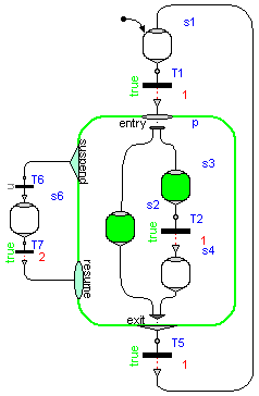
This component acts both as a composite step (having just one branch) and as a Step that has parallel branches that are executed in parallel to each other.
The details are summarized
here
in the tutorial. A typical example for the usage
is shown in the next Figure (component "p"):

In the following table different configurations of a Parallel component are shown:
use_inPort=true
 |
use_inPort=true
use_outPort=true
 |
use_inPort=true
use_suspend=true
use_activePort=true
 |
initialStep=true
 |
Extends from Modelica_StateGraph2.Internal.Interfaces.PartialParallelBase (Base class of a parallel component (including a composite step as special case)).
Parameters
| Type | Name | Default | Description |
|---|
| Boolean | initialStep | false | =true, if initial step (start state machine at entry ports of Parallel) |
| Boolean | use_inPort | true | =true, if inPort enabled |
| Boolean | use_outPort | false | =true, if outPort enabled |
| Boolean | use_suspend | false | =true, if suspend and resume ports enabled |
| Boolean | use_activePort | false | =true, if activePort enabled |
Connectors
| Type | Name | Description |
|---|
| Step_in | inPort[nIn] | If enabled, port for one or more input transitions |
| Step_out | outPort[nOut] | If enabled, port for one or more output transitions |
| Composite_suspend | suspend[nSuspend] | If enabled, port for zero, one or more suspend transitions |
| Composite_resume | resume[nResume] | If enabled, port for zero, one or more resume transitions |
| EntryPort | entry[nEntry] | Entry port for one or more branches (Step or Parallel components must be connected to this port) |
| ExitPort | exit[nExit] | If enabled, synchronization port for one or more branches (Step or Parallel components must be connected to this port) |
| output BooleanOutput | activePort | = true if Parallel component is active, otherwise it is not active |
Modelica definition
model Parallel "Composite or parallel step"
extends Modelica_StateGraph2.Internal.Interfaces.PartialParallelBase;

Modelica_StateGraph2.Internal.Interfaces.Step_in inPort[nIn] if use_inPort
    "If enabled, port for one or more input transitions";
Modelica_StateGraph2.Internal.Interfaces.Step_out outPort[nOut] if use_outPort
    "If enabled, port for one or more output transitions";
Modelica_StateGraph2.Internal.Interfaces.Composite_suspend suspend[nSuspend] if
    use_suspend "If enabled, port for zero, one or more suspend transitions";
Modelica_StateGraph2.Internal.Interfaces.Composite_resume resume[nResume] if
    use_suspend "If enabled, port for zero, one or more resume transitions";

Modelica_StateGraph2.Internal.Interfaces.EntryPort entry[nEntry]
    "Entry port for one or more branches (Step or Parallel components must be connected to this port)";


Modelica_StateGraph2.Internal.Interfaces.ExitPort exit[nExit] if use_outPort
    "If enabled, synchronization port for one or more branches (Step or Parallel components must be connected to this port)";


Modelica.Blocks.Interfaces.BooleanOutput activePort = active if use_activePort
    "= true if Parallel component is active, otherwise it is not active";

equation
// Handle conditional connectors
connect(inPort,  local_inPort);
connect(outPort, local_outPort);
connect(suspend, local_suspend);
connect(resume,  local_resume);
connect(entry, local_entry);
 if use_outPort then
   connect(exit, local_exit);
 end if;
end Parallel;
Partial compont to construct a parallel submodel via inheritance

Information
This is a variant of the
Parallel
component. The essential difference is that this
is a "partial" model. It is therefore not allowed to drag it. The only purpose of this
model is to inherit from it in order to construct a new model that is a special
Parallel component.
The Figure below shows a component ("s2") built from a PartialParallel component. As the diagram and the icon layer of the PartialParallel component does not need to be the same size, the user can benefit from collecting large subsystems in smaller closed Parallel components to improve overview and modularization of the full system.

Extends from Modelica_StateGraph2.Internal.Interfaces.PartialParallelBase (Base class of a parallel component (including a composite step as special case)).
Parameters
| Type | Name | Default | Description |
|---|
| Boolean | initialStep | false | =true, if initial step (start state machine at entry ports of Parallel) |
| Boolean | use_inPort | true | =true, if inPort enabled |
| Boolean | use_outPort | true | =true, if outPort enabled |
| Boolean | use_suspend | true | =true, if suspend and resume ports enabled |
| Boolean | use_activePort | false | =true, if activePort enabled |
Connectors
| Type | Name | Description |
|---|
| Step_in | inPort[nIn] | If enabled, port for one or more input transitions |
| Step_out | outPort[nOut] | If enabled, port for one or more output transitions |
| Composite_resume | resume[nResume] | If enabled, port for zero, one or more resume transitions |
| Composite_suspend | suspend[nSuspend] | If enabled, port for zero, one or more suspend transitions |
| output BooleanOutput | activePort | = true if Parallel component is active, otherwise it is not active |
Modelica definition
partial model PartialParallel
  "Partial compont to construct a parallel submodel via inheritance"
  extends Modelica_StateGraph2.Internal.Interfaces.PartialParallelBase(
    use_inPort=true,
    use_outPort=true,
    use_suspend=true);

  Modelica_StateGraph2.Internal.Interfaces.Step_in inPort[nIn] if use_inPort
    "If enabled, port for one or more input transitions";
  Modelica_StateGraph2.Internal.Interfaces.Step_out outPort[nOut] if use_outPort
    "If enabled, port for one or more output transitions";
  Modelica_StateGraph2.Internal.Interfaces.Composite_resume resume[nResume] if
    use_suspend "If enabled, port for zero, one or more resume transitions";
  Modelica_StateGraph2.Internal.Interfaces.Composite_suspend suspend[nSuspend] if
       use_suspend "If enabled, port for zero, one or more suspend transitions";

  Modelica.Blocks.Interfaces.BooleanOutput activePort = active if use_activePort
    "= true if Parallel component is active, otherwise it is not active";

protected
  Modelica_StateGraph2.Internal.Interfaces.EntryPort entry[nEntry]
    "Entry port for one or more branches (Step or Parallel components must be connected to this port)";
  Modelica_StateGraph2.Internal.Interfaces.ExitPort exit[nExit] if use_outPort
    "If enabled, synchronization port for one or more branches (Step or Parallel components must be connected to this port)";

equation
  // Handle conditional connectors
  connect(inPort,  local_inPort);
  connect(outPort, local_outPort);
  connect(suspend, local_suspend);
  connect(resume,  local_resume);
  connect(entry, local_entry);
  if use_outPort then
     connect(exit, local_exit);
  end if;
end PartialParallel;
Automatically generated Fri Nov 12 17:26:46 2010.
 Modelica_StateGraph2.Step
 Modelica_StateGraph2.Transition
 Modelica_StateGraph2.LoopBreakingTransition
 Modelica_StateGraph2.Parallel
 Modelica_StateGraph2.PartialParallel